HTTPster Update

HTTP (Hypertext Transfer Protocol) is the default protocol used to transfer data between a Web server and a Web browser. When you open Internet Explorer, Chrome, Firefox or Safari and type a URL in the address bar (for example, https://www.datayard.us); you’re actually sending an HTTP request to DataYard’s Web server requesting information; in this case DataYard’s homepage. When DataYard’s Web server receives this request, it searches for the desired information and responds to your Web browser with the appropriate information. This information is then displayed on your monitor and the HTTP connection is closed. If you were to click on any link within the home page, another HTTP request is sent to the Web server and it responds with the desired data and again displayed on your monitor.

HTTP is inherently insecure, meaning information is sent in plan or clear text. Why is this noteworthy? If a savvy person were to “snoop” on your Internet connection, they’d be able to read the data rather easily using simple tools found all over the Internet. This isn’t such a bother when you’re browsing for the latest football scores or reading up on recent events. However, if you’re paying bills, checking bank accounts or attempting to secure a loan of some type via an online finance tool, this becomes seriously concerning. The answer: HTTPS.

HTTPS (Hypertext Transfer Protocol Secure), as its name implies, is HTTP’s much more secure brother. If you were to type “google.com” into your favorite browser, you’ll likely see the address change and it’ll look like this…

Why is this, though? It’s because Google uses an SSL (Secure Socket Layer) certificate to encrypt data sent between their Web servers and your Web browser. Much the same can be said about almost any other Web domain that would be expected to serve up sensitive information (banks, online shopping, investment entities, utility companies that accept online payments, etc.). Without this certificate or HTTPS, if you were to complete an online shopping transaction and someone happened to be “snooping” on your device or Internet connection, they’d be able to see the details of your purchase in plain or clear text. Credit card information, shipping addresses and other details of your transactions would be wide open for the world to see. So how does HTTPS work exactly?

When an SSL certificate is purchased and placed on a Web server, the Web server holds a private key, basically an encryption algorithm that tells its public key holders how to decrypt the information its sending back and forth. Let’s take our first example of HTTP but this time we’re going to use HTTPS.

It’s time to pay bills and instead of using snail mail, you’ve opted to go green and pay online. You enter your vendors Web address in your browser, https://www.electriccompany.com. Immediately upon this request, Electric Company’s Web server will send your browser a public key, instructions on how to decrypt the encrypted information via the private key. Confused yet? You shouldn’t be. All this decrypting and encrypting is transparent to the user and is exclusively handled by the browser and server.

As you enter your credit card information and click “SUBMIT”, your credit card information, account details and other personally identifiable information is sent to the Web server within a snug, tightly-wrapped blanket of human-unreadable characters that can only be deciphered by the Web server and it’s private key. So the guy that’s been “snooping” on your Internet connection would only see a very lengthy and incoherent string of characters that would envy Da Vinci’s cryptex.

Now that you have a better understanding of HTTP and HTTPS, as well as their differences and advantages; how does one go about “securing” their Web site? It’s rather simple, actually and as more and more people conduct sensitive business in our technologically endowed world, certificate authorities (CA) are making this process even more streamlined than before.

Companies like VeriSign, GeoTrust, DigiCert and GoDaddy specialize in the sale and deployment of SSL certificates on a global scale. A user would simply purchase an SSL certificate from any of these CA’s then install the certificate on the appropriate Web Server(s). Once the installation is complete, any browser requesting information from that Web server would then have the benefits and peace of mind that all the transactions would be safe and secure! If you’re not up for the task just let us know and we’ll be sure to take care of everything giving you a wonderful gift, peace of mind.

Roomberry Project v.10

With just one week remaining, we managed to have a successful week tying everything together. Like Owen said last week, we ran into issues with the RFID. We had finally gotten it to work on our makeshift electrical tape track with a few sensors along the way, and decided to move it along to a practical application. However, that’s when we realized that our tags being 3mm, the antenna was too small for the signal to overcome the metal floor tiles. This week we received our color sensor as an alternative. We decided that since we can’t use any form of wave communication, our best bet was to either change back to QR (which we really didn’t want to have to do) or find an alternative. This color sensor has worked wonders thus far. We are able to pick up readings via lux, or lumens, and convert that into a 6 digit RGB hex code. With this we can set it up exactly like our RFID tags. We will be mapping out the data center similar to how we had tags, which is to have a temperature reading taken at the front of a server cabinet. Not only will this allow more precise temperature data, but it will also be a sort of location finder for the roomba. IMG_3587

With one week remaining, there is still a decent amount to be done, but we feel confident that once we leave, there will be a stable platform for the rest of our peers here to work with and improve upon when necessary. With our downtime on Monday before the color sensor came, we were able to get our preliminary temperature and humidity data uploaded using phant. The link for  that, which will be updated real-time once this is permanently running, is here. Next week our main goal is to, well, finish the project. We need to implement our new color tags, fine tune any bugs, and get our data uploading to local servers here for ease of access.

Stay tuned for our final blog post next Friday!

Roomberry Project v.9

Monday was yet another productive start to the week for Jim and I. More testing was done on RFID tags, and we fully ironed out our IR line following. However, on Wednesday tragedy struck.

Ever since we first had started messing around with RFID tags, there have been issues. with our 125kHz reader, we could never find a tag small enough to be used with our floor tiles. To solve the problem, we upgraded to a 13.56MHz reader and nifty little three millimeter tags. However, we were never able to get the reader to properly identify the tags. So instead we bought a different, more widely used version of the reader that came with a pre-made Python library. Once we got that up and running, we thought we were in the clear, but on Wednesday we found that due to the small antenna on the RFID tag it cannot be read if it is within one centimeter of the metal floor tiles.

Because the deadline of the project is drawing near, Jim and I decided to save both money and time and scrap the idea of using RFID in its entirety. Instead, we will be focusing our efforts on two ideas that we had as possible replacements.

The first idea we had was to give QR codes a second chance. If we can minimized the amount of time each poll takes, we would be able to make a track of QR codes along the floor. Our second idea is to use a color-sensitive light sensor in combination with colored tiles to determine the next command.

Next week will be hammering out these new navigation methods, wish us luck!

Roomberry Project v.8

This past week brought a great deal of success for myself and Owen as we continue working towards our final goal for this project. Last week we obtained various pieces of hardware, but some of those such as the RFID reader and USB hub for the Raspberry Pi zero didn’t want to play nicely.

Coming into this week we had set a goal for ourselves to have all of the parts put together in an attempt to have our first working prototype by the end of next week. Hardware wise we were able to achieve that goal, but not without some frustrations. We started the week with an RFID reader, ICSH008A, based off of the popular Mifare RF522 card, but realized that we could only find documentation in Chinese and on lackluster Ebay pages. Lesson learned – buy the real thing! We ended up going with the Adafruit PN532 breakout board and had a huge breakthrough with our tags. Not only can it read any Mifare card, but it also spits out the UID on our 3mm tags mentioned last week without any additional code or having to write to it.

Slack for iOS Upload (3)
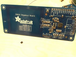
On top of getting our RFID to work, we also were able to get the Pi zero USB hub to work. This wasn’t a huge issue to fix, but once we hooked it up to the Pi we were worried that we might not be able to use a port on it for serial communication. On the Pi 3 we were using before there was a dedicated serial port, COM0, which we weren’t sure the USB hub had. However it did, and we were able to continue on with using the Pi zero.

Slack for iOS Upload (4)
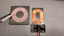
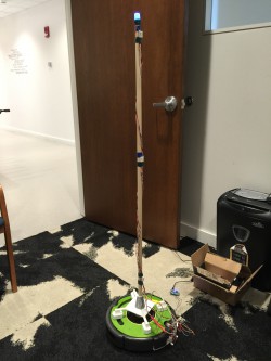
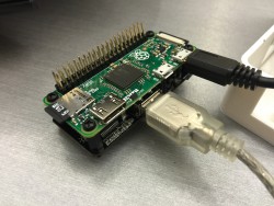
After some preliminary testing with the new inductive charging, we were able to confirm that it does charge our LiPo battery at a much quicker rate, and more efficiently, than our last set of coils. As of today we’ve also done some testing with our IR and making turns with it, and have decided on a new process that will eliminate the use of RFID tags to turn the Roomba. We will strictly use the IR for movement, and RFID for data points and positioning. Our current IR has 6 sensors; we decided to keep the black line centered between sensors 3 and 4, rather than correcting to other sensors. From there, if the Roomba reaches an intersection and sensors 1, 2 and 3 are covered, it will make a 90 degree left turn. If sensors 4, 5 and 6 are covered, it will make a 90 degree right turn. If sensors 1-6 are covered, it will make a 180 degree turn and continue on path.

We take our success this week with a grain of salt, as we are now reaching the tedious testing and fine tuning phase which will likely take some time. We hope to have complete IR control as of next Friday, and can implement the RFID in the following weeks. Owen and I are proud of how far this project has come along and that we are near reaching a final product, stay tuned for next week’s post!

Roomberry Project v.7

So this week’s blog post is going to be a bit longer than the others because I’ll be talking a lot about the various hardware upgrades that Jim and I have gotten for the project, and our thought process behind them.

The first and probably most exciting upgrade for us was going from a Raspberry Pi 3 to a Raspbery Pi Zero. We’ve been using a Raspberry Pi 3 for the past couple of weeks in order to test things like the IR sensor, the RFID reader, and even the camera to read QR codes (even though we’ve since abandoned it). However, Jim and I knew that we wouldn’t be using the RPi 3 in the final version of the project for two reasons. Firstly, the model 3 is fairly large. We have to fit all of the electronics inside of the modified vacuum bin of the Roomba, and it was a very tight fit putting the RPi 3, the serial-USB connection, and the IR sensor alone. Secondly, we were worried about the battery consumption of the model 3. At nearly a third of the size and one sixth of the power consumption, the RPi Zero easily solves both of these problems.

However, even though using the RPi Zero was the best solution to our problems with the RPi 3, it didn’t come without it’s problems. The biggest being the lack of USB ports. With our current setup, we need to have two open USB ports. One will be used for a WiFi dongle so we can collect sensor information in real-time, and the second to use to talk to the Roomba. Simple solution to this was to get a USB hub. The one we found is actually really neat, it fits nicely on the underside of the RPi and just screws into the mounting holes. No soldering needed at all! Now that we had figured out the issues with the RPi, we could move on to some of the problems with our ‘track’ that the Roomba would follow.

A few blog posts ago, we discussed the use of an RFID reader instead of a QR code scanner. The RFID reader that we had tested operated on the 125 kHz range, and its tags were roughly the size of a credit card. Eric and David expressed their concerns with having a dozen or so credit card sized tags lining the floor of the server room, so I looked into the possibility of using smaller tags. A week later, a package arrived containing what I believe to be the smallest 13.65 MHz RFID tags that we could buy. Measuring at 3 mm square, you can clearly see the size difference between the two cards.

RFID

Again, this upgrade didn’t come without its own problems. Because we’re using a different frequency tags, we needed a new reader to be able to scan them. Our old reader was very plug-and-play friendly, only needed a few lines of Python to get it up and running, but our new reader is a bit of a mystery. The only code we can find to get it running is for Arduino, and even then we’re having trouble scanning the tags. Next week we plan to look into reading and writing to the tags.

The last upgrade that Jim and I got this week was for our inductive charger. We noticed that the rate of charge was a bit slower than the rate of consumption on the RPi 3, and we wanted to be sure that the RPi would be able to run 24/7, so in combination with a greatly reduced power consumption (RPi Zero), we beefed up our inductive charger. This should ensure that we’ll be able to keep a constant supply of power to the RPi Zero.

charging

That about wraps it up for this week! Next week, along with getting our new RFID reader up and running, Jim and I will be thoroughly testing the Roomberry on a makeshift track to iron out any issues that could come up regarding line-following and RFID tags.

Roomberry Project v.6

This past week has been yet another successful one for Jim and I. We’ve been making progress on the mounting solution for our DHT22 sensors. We wanted at least three sensors picking up data from different heights, so Jim 3D printed a series of parts to mount a 3/4″ dowel rod onto the Roomba’s body. We’re still fine tuning how everything will fit together, but he has a pretty good prototype right now. Next week when we get our fancy new 3mm RFID tags and a USB hub for the Pi Zero, he’ll be working to find a finalized interior setup for all the electronics in the modified dust bin

.IMG_20160722_155739889_HDR

On the software side of things, I’ve still been fine-tuning our line-following logic as well as preparing for the use of RFID tags. As Jim said in an earlier post, we won’t be using black electrical tape as our guide, but rather the cracks in between the tiles themselves. This leads to the issue of the crack being slightly smaller than the distance between the IR line sensors, so there might be readings where the line doesn’t show up at all. I think I’ve found a good balance between speed, turn correction, and the length of time it will time out at if it hasn’t found a line.

Before I left on Wednesday, I ran a little program to drain the Roomba’s battery completely, and to measure the amount of time it takes to do so. From what I found, the battery drains (with the wheels moving, and the OI in Full) at a rate of approximately 1% every 4.75 mins. This morning I ran the same program, except to measure how fast the Roomba charges. I found that with the OI in Passive, the Roomba charges at a rate of 1% every 1.5 mins. We’ll use this information when planning the route the Roomba will follow.

Next week, Eric and I will be looking into the possibility of using Slack as the method of turning off the Roomba for server maintenance as well as sending alerts that the Roomba might be lost, running low on battery, etc.

Roomberry Project v.5

Another successful week has occurred for us working on our Roomberry Project. After successfully implementing our serial tether on Monday, we started putting together the rest of the pieces we had been working on. The biggest improvement came from the addition of our line following IR sensor. Our roomba now follows dark lines, specifically black electrical tape at the moment. The goal for this is for us to darken the lines between our floor tiles in the data center, and have the sensor follow that. The biggest hurdle thus far with that idea is the thickness, or lack there-of, of the space between the tiles. Owen will have to fine tune his code in order for it to stay on track. With the help of David and Eric, we were also able to successfully 3d print a new caster bin, replacing the vacuuming tray, in an attempt to have a spacious place for the hardware. After 3-4 tries, and a roll or two of ABS, it was printed perfectly. The main focus from here on out is to fine tune the IR, and continue to work on a feasible solution for the roomba to know when to take readings and upload them, as well as turn commands. We originally thought to use QR codes with the RPi NOIR camera, but decided we might have better luck with an RFID reader.

There is still much work to be done, but there will be continuous progression on this project the next 5-6 weeks.

Roomberry Project v.4

Coming off of the holiday weekend, we felt pretty good about last week’s success’. We were able to setup our hard-line serial tether on a test board, as well as set it up on a more permanent prototype board. However, a few issues occurred with our permanent version. After we put together the first board, we were running voltage measurements and were getting fairly strange numbers out of our 78L05 voltage regulator. Rather than getting a steady 5v out, we were only achieving around 2.25-2.3. After deciding to scrap that board and move on to a new version, we overcame the voltage issues, but ran into another problem with a faulty MAX232 transceiver chip. Over the weekend we will work to fix that issue in hopes to come back Monday with a completed serial tether.

In the mean time, Owen was able to make significant progress on our IR line-reading array. Our obstacle to work around line reading in the data center is that we do not want obvious lines of electrical tape or like objects running over the large gray tiles. We were able to fabricate up a better solution and we hope to improve on it while working towards our serial tether. Lastly, we also made great progress on setting up our QR code reader using a Pi NOIR camera. In partnership with an IR LED, this camera should be able to pick up QR codes of relatively small sizes, and relay the info to our bot, causing it to go in whichever direction it needs to be going.

Next week we plan on having our serial tether working, and in turn, will be able to get our roomba following lines in an attempt to setup a mock version of our data center path.

Roomberry Project v.3

Coming off of the rather disappointing results from last week in trying to get a serial connection set up between the Roomba and the Raspberry Pi, we have been able to make loads of progress. Jim made some great headway on getting a hard-line serial tether set up. We were able to successfully tether the Roomba to a laptop as well as a Raspberry Pi and communicate back and forth between them. Right now he is working on getting the circuit into a permanent state so we can start focusing our efforts on getting a working prototype. On Wednesday, we came up with a list of the next couple of goals that we need to reach.

The first and most important goal moving ahead is to figure out where all of our sensors and circuits will be sitting within/on the platform. The solution we came up with was to 3D print a redesigned vacuum tray that will be able to hold the Raspberry Pi, the serial hard-line, and batteries all in one place. Unfortunately, the estimated print time for our tray is slightly over eight hours, so prototyping and experimenting with various designs will be a slow process. However, once we get all of the hardware in a close to finalized place, the software work will go a lot smoother.

One of the last major software hurdles will be getting all of the pieces of the platform to start communicating with each other. Luckily, all this downtime in waiting for parts and having an unreliable tether to the ‘brain’ of the Roomba has given me plenty of time to experiment with the other sensors and parts. I have been able to transfer the IR line reader and DHT22 sensor back onto the Pi with relatively no issues. Right now, the state of the software is that I have everything working, but only by itself. I have a Python script for the IR sensor, a different one for the DHT22, etc.

Next week I’ll be working on combining all of these separate parts while Jim does the same, but on the hardware side of things.

Roomberry Project v.2

This past week had major ups in downs in terms of our project’s completion. We had setup a proper serial port connection in order to communicate with the Roomba via Pi, however early in the week we ran into some hurdles and could no longer communicate with the Roomba. Numerous attempts were made to solve this issue not only by us, but by fellow co-workers as well, but to no avail. Early next week we will attempt to make a hard-line serial connection from laptop to Roomba in a better attempt to solve the issue. With the lack of the Roomba platform we were still able to setup some of the other major parameters of the project. We have successfully setup a digital IR line reading device on a separate platform, as well as a DHT22 temperature/humidity sensor. In the following weeks we plan on setting up a QR code reader via a Pi NOIR camera to give us some reference points as to where our bot is in the data center.

The major task for next week will be setting up the hard-line serial circuit, and potentially getting some semi-permanent circuits setup on whichever platform we end up using.